Tuesday Tutorial: Now in 3D!

25 08 2009

Now that you have a completed CAD base map, with all of the elevation edits needed, you have just one final step before you can Import your design into SketchUp.  If you used a construction line hidden layer, turn it on, and every other layer off.  Then delete all information off of the trace layer, and delete the trace layer itself.  The main reason to do this is because when CAD files are imported into SketchUp, if a line exists in the same spot on two different layers, the line will be assigned to one layer, and the other will have the area blank.

As a quick software note: One of the main differences between SketchUp standard and Pro is that while CAD can be imported into either version, you can only Export non-CAD files in Pro.  So if you are planning an rendering in SketchUp, or using photo editing software to tweak, either version of SketchUp will work fine.  However, if you want to export into 3D Studio Max for higher end light and material rendering, you will need the Pro version.

Now its time to fire up SketchUp and get cooking.

Step 1: Importing

Once you have SketchUp running, the actual importing of the CAD file is pretty straight forward.  Open the File drop down, and select Import.

ImportMenu

Now navigate to the area where you saved the CAD file, change the file type to import to .dwg, and import your file.  If you get a message about your CAD file being invalid, its possible that your CAD release is newer then your SketchUp, so just save your CAD file back to 2004 or 2000.

One of the nice, and not so nice, things about SketchUp is that it imports layer states along with the layers, so if you had all of your layers turned off when you saved your CAD file, they will all be turned off now.  To turn them back on, go to the Window and select Layers.

layerdropdown

This is your layer navigator.  This will be a window you want to keep open, as what ever layer has the radio button checked is the layer that what you are drawing will be on. Turn on all your layers, and then zoom to extents and select the top view, and you should see something like this:

newimportallon

Congratulations, you now have an Imported SketchUp model, its time to save, and move on to the topography.

Note: Save early and often in SketchUp.  For as fun, quick, and easy, as it is, it is buggy as all hell, and crashes fairly often, so save yourself the grief of losing 45 mins of work.

Step 2: Let the technology do the work

The first thing to do is turn off all your non-topography layers.  Once you do that, Take a quick look around in your model.  You should be able to get a good feel for the topography you have created, and the type of landscape you have.  You may notice a few areas that you want to tweak.  You should do that now.  I noticed, when looking out from what would be my train station, that the two hills that flank my view are lower then I would like, and that the topo is not going to carry as far out as I would like.  You can either jump into cad, fix the problems, and re-import, or add and move lines to fit your needs.
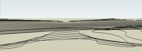
needtofixlines

You also may notice problems like I did, where I have a hill top that is supposed to have two peaks.  I made two separate contour loops as seen below (blue are the higher contours).
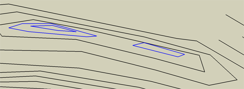
needtofixvalley

The problem is that SketchUp will simply create topo straight across between the two, as there is nothing pulling the form back down between them.  This can be fixed by quickly adding a line or two that will outline where you want the low point of the pass to be.

Now its time to have SketchUp do some work.  First open the Window drop down, and select Preferences.
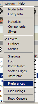
PrefMenu

Then in the left side select “extensions”, and turn on sandbox.

ExtentionMenu

That will add the sandbox toolbar to your display.  ensure that you have all layers off except topo, and that you have the topo layer selected with the radio button, and do a quick save in case the program crashes during the next step.  Now click on the button on the far left of the toolbar- “From Contours”.

sandboxtoolbar

At the bottom left edge of the screen, there will be a progress bar.  Depending on your processor and the size and detail of your model, it may be quick to fill, or take quite a while.  If you notice the bar suddenly stop moving, don’t touch anything.  SketchUp is very touchy, and its likely that your computer is using so much power to create the topo that it doesn’t have enough left to move a —->—- further to the right.  I know, it sounds scary, but in SketchUp, if something starts to freeze up, don’t start clicking, just put the mouse down and go get a sandwich.  If you click you may cause a crash, but if you leave it alone, you have a good chance of the computer catching up with itself and then you can save ASAP. Once its done, turn on shadows to get a little better lighting, and it should look something like this:

newlytopoed

Step 3: That shouldn’t look like that…

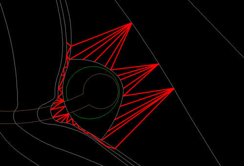
Now take a close look at your model.  You should be able to see all on the topo lines you drew, with a surface in between them, but you will likely see some areas that look… off.  Two key things to look for are places where you see to many lines (Red), or topo lines disappear for no reason (Blue).

topoproblems

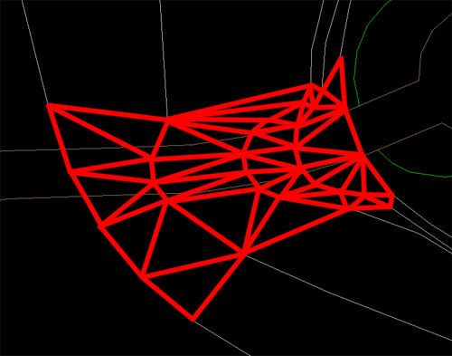
As you can see with the shadows turned on, missing lines come from an area where SketchUp arbitrarily decided to skip sections of topo lines and take a shortcut.  The extra lines happen when SketchUp forgets how to draw a flat surface in a small area, so it freaks out and starts throwing lines across the area.  Go to the View drop down and turn on “Hidden Geometry”.  You can now see all of the polygons created by the software.

Double click the topography you created, and you’ll notice that the hidden lines now highlight when you mouse over them as you are in component editing mode.  the first topo fixes you are going to do are the quick and easy ones.  You might notice an area where a topo line or two are covered, like this:

needtoturnhidden

Now you are going to use the tool on the far right in the “sandbox” toolbar- “Flip Edge”.  This takes a diagonal line and rotates it to the opposite diagonal.  Here is an animation of flipping the lines, one by one, to correct the topography.

turnani

Note: For some reason I cannot get the GIF to play, even though it does in the wordpress blog text window, so I don’t know what is going on.  Check it out here.

Once you go around and fix all of the areas you can using this method, you will have the more complicated work to do of manually adding and removing polygons, but that will wait for next week.



Tuesday Tutorial: Building your base

20 08 2009

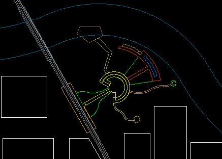
When you start your 3D model, you start with a cad base, just like you have for your plan graphics and for your Bid Set.  However, there are some tweaks that need to be made, and things you have to pay more attention to then normal.  In this tutorial I’m going to take you up to the point of bringing your model into SketchUp.  Next time we will get into tweaking topo and base modeling, and then after that, the fine modeling level, and adding plants.  But for now, we are focusing on the base, as without a good base, the modeling process will be much more difficult and time consuming.

Note: When you use CAD, use Polyline, for the love of god.  It is only in EXTREMELY rare cases that line works BETTER than poly line, and this is NOT one of them.

Step 1: Clean up your normal CAD base

To start, open your normal CAD base and save a copy of it in a new folder.  Once you have your copied CAD file, there are a few fairly simple things you can do to clean up your base.  The first is to carefully go through and create new layers based on the different materials you will have in your model, and you should name them based on what material they will be to reduce confusion.

cadlayers

A key point here is to make sure you have a unique layer for each of your materials, as the layers will carry over to SketchUp.  Once you put everything on the correct layer, make sure all your corners are square and your polys close.  You are going to have to close them eventually anyway to make them into surfaces in SketchUp, so you might as well do that now in the friendly confines of CAD.

linebase

Step 2: Topography- think like a computer, one triangle at a time

Now its time to add topography.  There are two main issues you are going to have to address with topo: thinking about how the computer will create the surface, and thinking about making what goes on those surfaces.  This is the basic topo for the fictional park design I am working with.

topolinebasic

The first thing to realize is how SketchUp (or any other program) will create your topography.  As a quick intro/refresher- all 3d models are comprised of polygons- more precisely, triangles.  That is because 3 points makes a plane, and computers, as amazing as they are, cannot make true curves.  They can make thousands of tiny angles, but not an actual curve (there are ways to fake it more, but its still really a post production fake).  That is why when you make a curve in CAD and then zoom in it is suddenly angled lines that are kind of in the wrong spot.  Getting back to the point- your computer will make the smooth, rolling landscape by making a bunch of triangles and “softening” the edges, but it is still made up of triangles. These triangles are made by drawing lines from intersections on one line to intersections on another line.  For example, with these lines:

topoexample

This is (hopefully) where the triangles would be made:

topoexample2

This means 2 main things for your drawing.  First, and easiest: the further the camera is, the less detail that you will see, so by simplifying the lines that the triangles are made from, you reduce the number of triangles, and decrease rendering times.  So, when you are getting to areas that are far out of your model, and don’t need a lot of detail because they will act simply as context, you can often get away with making those smooth curves into sharp angles, and get nearly the same result for far less CPU power.

The second, and more tricky point: if you have a flat terrace, on your topography map that is shown by an area with a bigger spread in its contours, because we interpolate a steep slope suddenly being flat as essentially a level slope, even if the contours imply a 5% slope, because the slope is likely steep beyond the last “steep” contour.  However, the computer only sees what you put in, and cannot interpolate unevenly spaced contours, so it will have a slope that is steep from one contour the next, and then makes a hard turn to a 5% slope, and then a steep drop again.  Because of this, you have to edit your contour layer, and break one of the cardinal rules of topography- you are going to have a contour line split and then rejoin.  to create a truly level area you are going to have to surround the entire level area with equal contour lines, forcing the computer to see the contour lines your mind is reading between the lines on the map.

Level area the way its drawn on a map:

terracebadblank

The way that would be interpreted by a computer:

terracebad

The “fix” by breaking the rules:

terracefixedblank

The new triangle map (level area skipped for clarity):

terracefixed

Step 3: What is that path going to look like exactly?

The last big complication to 3d modeling on topography is getting your paths and areas that overlap topographic changes to look right on the slope.  The problem is, again, the fact that the surface of the ground will be made of triangles.  this becomes an issue because your triangles may not line up with the edges of materials.  There are a few things you can do to address this.  First, you could simplify your topography so that a minimal amount of it intersects site amenities, as I was able to do in my thesis project, as there are not many large grading changes other then wetlands.

university

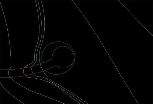
At times, however, that is not a viable option, and you need to be able to control what your slope looks like on a given face.  To do that you need to ensure that a given section of slope is laterally level.  The first step for that is to edit the contours so that the slope crosses the area in a straight line perpendicular to the slope.  This is what my topography looks like after I add my loops for level ground:

curvingtopopath

You want to change all of the sloping areas here:

curvingtopopathhighlight

To look like this:

curvingtopopathfixed

Once you do this, you wait for further fixing until you are in SketchUp, and that will come next week…

Step 4: Elevate to a New Level

The next thing you have to do is elevate your topography and items to the levels they will be at.  In AutoCAD, you want to open the properties window for each contour line individually.  Once there, you will see an option for “elevation”.  This is where you input the height of a given contour line.  Go through each contour line, and object and assign them to the appropriate elevation.  I personally like to also change them to a set color, like magenta, so I know what I have moved.  Then once everything is adjusted you can select all and move the color back to “by layer”.

elevation

magenta

magenta3d

Once you have everything moved to the correct elevation, you can change the color back, and finish the fix for uneven paths.

Now its time to import into SketchUp and let the real fun begin…


Tuesday Tutorial Primer: So you want a 3D model…

11 08 2009

The first thing you have to figure out when you want to make a 3D model for a rendering is if you really want a 3D model rendering.  This decision is similar to the question of if you want a hand rendered plan or a Photoshop plan.  There are of course aesthetic reasons involved.  Both can work extremely well, and look amazing, but by understanding your client, your design, and the look you will get from either method of rendering you can make the choice of which is best for you on a given project.

There are more then just aesthetic differences to be looked at, however.  Ask yourself what the purpose of the model is.  Is it for images of a few conceptual designs, or for a final design proposal?  If you are looking to do more of a conceptual design presentation, then you may want to go with a hand drawing, as they are going to be relatively quick and easy, where a 3D model, even using software like SketchUp will be somewhat drawn out and difficult, as a lot of time will be spent re-making the same things multiple times in NEARLY the same way.  One of the reasons to go with a 3D model, in any level of design, is because of the ability to animate the design to increase the understanding of the place by allowing the client to “walk through” the site.  Also, if you think you may want multiple angles of a space, or think the client may want to see a few additional places later on, you may want to make a 3D model, as you can always add additional camera and have a new rendering for the cost of running one of your CPUs for a few hours overnight.  In the final design phase it may be far more worthwhile to create a 3D model as if a little extra time and the right software some pretty amazing images can be created.

Conceptual Hand:

sketchdemo

Conceptual SketchUp:

memorial

Final full 3D Rendering:

3DDemo

The third issue is purely a question of time: is it worthwhile to invest the time into a 3D model, or does it make more sense to do hand sketches.  One of the ways computer models are different from computer plans is that a computer plan is extremely easy to edit, giving itself a big advantage over hand graphics which must always be made from scratch, and many 3D models are difficult if not effectively impossible to edit.  Another time factor is the issue of the current hardware you have in terms of computers.  Go back and check out my post of computer hardware, and see if you have a suitable system for 3D modeling.  It can be done on almost any machine (I can run high end stuff on my 633 Mhz Celeron with 256 or RAM and a 32 Meg TNT graphics card if I’m feeling silly), but some machines will not only render slowly, but will slow down the creation process as well (See: Machine I just mentioned) to the point where you lose any hope of cost effectiveness.

There are some special uses that 3D models suit themselves to much more as well.  If you want to create a new element in an existing location, you can re-sketch the whole scene, or you could create the new element in 3D, and place it into the photo of the existing site.  This can be an extremely effective rendering, and isn’t something that has to take a lot of time to do.  The model for the following image is a fairly simple SketchUp model with careful lighting and camera placement to create the right angle and shadows, but was a very quick project for the quality of the end product.

bluff

In the coming weeks I will take you from a CAD plan to a conceptual model, and then off to higher end software such as Maya and 3D Studio Max for better textures, lighting, and reflections, using my new website as the structure.  For the time being, pick a small simple design you have, and, if you do not already have them, put the design into CAD software.  This CAD basemap will be the basis of our design, so close all your lines, and keep some decent layer organization.  Next week I will address the CAD file you will import into Sketchup, and in the weeks after is when the real fun will begin.


Next week on Design + Tech…

5 08 2009

Next week the Tuesday Tutorial will return from its 3 week vacation with theme projects.  Next week, I’m starting on 3D visualization tutorials as I build the framework my new Flash based website.  That way you get to see a project I’m working on from start to finish over a few weeks, and then you get to see the real thing up and running, which I think will be a nice change.  Let me know if you have any issues in particular that you’ve had trouble with when doing landscape renderings, and I’ll be sure to address them.

For the time being, have fun looking at my current good-but-needs-reorganization website here, and see you Tuesday!


Video Games and the creative professional

4 08 2009

I can admit it, I’m part of the relatively new demographic of video game players.  I’m in my late 20’s, I have buying power (until the economy went berserk), and I own a PlayStation3 and a Wii, and every home Nintendo console since the original NES.  I enjoy games ranging from Gran Turismo (a racing simulator), to Burnout Paradise (a crashing simulator), and from LittleBigPlanet (an adorable platformer about small stuffed sack-people with stickers) to Grand Theft Auto 4 (a game where you try to rise up in the world of organized crime to live the American dream).  However, there is one thing I am always looking for, and never quite able to find: a game that satisfies my creative juices.  Many games keep me amused for a few months, maybe more if there was a way to hack the game directly (I’m looking at you Sims), but none has really kept my occupied fully for the long haul.

The problem is, through my increased knowledge and skills with things like AutoCAD and Sketchup, the creation tools included in any game are FAR to limited and always end with my being frustrated at trying to find work-arounds for seemingly simple things.  It takes the fun in creating a customized level in LittleBigPlanet and drowns it in the work of trying to stay within the programmed physics of the game.

Imagine this: There is a new design competition to design the future Central Park in New York.  They want you to imagine New York City in 200 years, in whatever way you want.  It could be after most of the island is flooded by rising sea levels, it might be choked with smog, or it might have 200 story buildings with roads that are all triple decked.  The historical society just re-found central park, and wants someone to turn it back into a cutting edge park, for the people of the future.  Blank slate, bold ideas, and you can submit your entry in any form of media you want.  *Note To Self: Find/Start a design competition like this!*

Two months in you get the Q & A packet, which includes a few rules amendments: You now have to create the park using the original topography and road layout, and all submissions must be on two 24×36″ poster boards, with their long edges aligned.

Suddenly you realize every idea you come up with either will not work or it needs to be somehow fudged to fit in the tight constraints.  The great design elements you had that shifted beautifully over time now have to show as static images instead of as living art.

This is the situation that invariably finds its way to me with any creative game.  I cannot tell if it is simply that I am spoiled by amazing tools like 3D Studio Max, or if non-designers feel the same way.  For any of you designers who are looking for a relaxing way to stir up some creative juices, or non-designers who are wondering if they really are as creative as they think they are, I’m going to start writing some reviews of my favorite creativity involving games.  From LittleBigPlanet, to The Sims, to Half-Life Mods.

Do you have any favorite creative games that you think I should try? Do you feel like sometime soon there will be a game who has enough creation power to allow it to be used for client presentations?  Or do you just want to know what the appeal is in spending $400 on a piece of hardware and $60 on a game that gives around 40 hours of entertainment?  Either way, let me know!  To play us out, a trailer for the upcoming Scribblenauts, a game I hope to own and review for you all soon.

Vodpod videos no longer available.