An Advanced Course in PC Hardware: $1,000 Performance PC with Style- Part III

23 10 2012

So far I have given you a break down of what I need overall, and most of the system specifics. Today, I am going to run down the rest of the build.

Component #6: Power Supply

Part of planning for it is getting enough power.  New Egg has a calculator ( http://c1.neweggimages.com/BizIntell/tool/psucalc/index.html) to help you figure out your power supply needs. One thing to keep in mind is to look at both what you are building now, and what your optimal load out is.  I built MY machine knowing that I was going to overclock my PC and add a second graphics card, so I got a massive power supply.  This machine will not be overclocked, but might get a second card, so I will plan ahead for it.  I put the specs for the build in (I put a performance MB in to play it safe), and got a moderate 477 Watt rating.  This is fairly middle of the road, but already can give you a sense of one of the advantages to building your own system vs. buying a pre-built with plans to upgrade later.  Pre-built systems often have the smallest power supply possible, so if you want a new, or second graphics card, you are also buying a new power supply.  So for a baseline, right now, I need a 500 Watt power supply.  If I add that second graphics card, and go to 4 sticks of RAM? 674 Watts.

Now you know the size you need, but how do you pick one? Hell if I know.  This is where looking at customer ratings is key. New Egg is pretty good about it’s ratings, actually sending out emails asking for reviews of items you have bought from the site, and when looking at the text reviews you can choose to only see verified owners (the people who bought the component from New Egg).  Take the Corsair brand TX750. I picked a Corsair because they are a well known brand, and I bought one of their supplies for my own build.  This has enough plugs to run two graphics cards, and enough power to run them, plus a second optical drive if I go nuts. The second thing to do is look at the ratings. I always start by reading the low rated reviews first. This will give you an idea of if people had the power supply frying on them after some use, if people were getting units that were dead out of the box (therefore not hurting other components, and returnable), or if people were buying the wrong thing.  This has a rating of 4/5 with 300+ reviews, 47 of which are 1/5. About 1/2 of the bad reviews were for DOA units (which seems to be fairly average), and some more had issues running out of the box and then died.  I’m not to worried, so I would still go with it, but this is where you have to just do some homework, pull up some alternatives, and see how things compare to each other.

Component #7: Hard Drives

As I mentioned before, the trick with a hard drive is finding the balance of speed, power, and price.  What some people don’t think about is the fact that this isn’t necessarily an all or nothing game.  If you need a LOT of space, and have a moderate budget, it doesn’t mean you are doomed to slow speeds.  One of the more popular things now is to get two hard drives.  One, a very large, moderately fast, but affordable drive to keep all of your files on, and most of your programs on.  Second, you get a smaller, much faster Boot drive (What they Operating System boots off of).  Depending on the size, you may also be able to put a few of your more important programs on here.  The key here is to remember that programs, when it comes down to it, are massive libraries of files.  When you use something like Photoshop  every-time you decide you want to use a filter, it needs to run the program for that filter.  Unless the filter’s program is in the RAM because you are using it for a second/third time, the computer needs to run around, find that part of the program, and run it.  If you have the program on a slow drive, it will take a bit longer to find and retrieve. However, if you are running thousands of these subroutines a day(which if you use one program often, you probably do), this will add up.

So, my advice would be to get one large traditional Hard Drive, and one smaller Solid State Drive to boot off of.  For the large drive, I am picking a Terabyte- it’s what I got for my build, and 2 years of Photoshop and 3D models later I still haven’t had to run around clearing space. It’s a beautiful thing. For the main storage drive I am selecting the Western Digital 1TB Black SATA III.  Western Digital and Seagate are the longtime brands for Harddrives that I tend to lean towards, and with a 5 year limited warranty,  2000 reviews averaging 4 /5, and a forty dollar discount at the moment, that’s good enough for me.

The Solid State drive I would shoot between 50 and 100 Gb.  This will be enough to take your O/S and a few programs, but shouldn’t be getting into the insane price ranges.  For this build specifically I want SATA III for at least the SSD, as that will allow me to take advantage of the faster drive speed with faster data transfer speed (When in doubt, look for bottlenecks in speed.)  Right now on NewEgg I can get the OCZ 2.5″ SATA III 60Gb (AGT3 model).  It is a moderately priced 60 GB SSD drive from one of the most well known SSD makers around.  This drive has 4/5 on NewEgg with 546 reviews, and its on sale for $62.

Misc.

This stuff is based a bit more on sale prices and brand name/reviews for me, so it’s pretty flexible.  You need a Media drive, and a wireless card, plus a mouse, keyboard and monitor(or two) if you are building a rig from scratch.  You may decide that you want to go with a Blu Ray drive, and forgo the burner option, or you may want to pony up the big bucks so you can burn BluRays (burner’s are in the $70-$130 range), but I am going to stick to a simple DVD-RW.  Realistically, find a drive from a brand you know, with decent reviews, that is cheap.  You should be in the $15-$25 range with no problem.

When you get a wireless card, the main thing to keep in mind is what your signal needs are. WiFi is rated as A, B, G, or N. A and B are kind of hard to find, and slow.  Today, you will mostly see routers and cards that are G, or N.  One good thing is these are all backwards compatible to the less powerful ratings (A is lowest, N is highest).  So if you have an N router and a G card, or a G card and an N router, it will still work, it will just be throttled to that G rating.  For most everyday use, G is fine. However, N is roughly 10x as fast, and has 2-3 times the range. So if you are moving big files, especially within a local network, or if you have a tricky time getting a great WiFi signal, move up towards N for both your adapter and your router.  I have a G router, and this is a local work machine, so it won’t be downloading any movies either, so I am going to stick to a simple G card (PCI Express) for around $20.

Another thing to keep in mind: the number and configuration of the PCI slots on your motherboard. Because I went with the Micro-ATX, the board I picked only has 3 slots, which are arranged in a way that means if I do run two graphics cards, there will not be room for my WiFi card.  One solution is to get a USB adapter, another is to buy an ethernet cord and hard-line your connection.  Its not a huge issue, but it’s an issue that you need to think about before you start buying things.

Picks:

CPU: i5-3450                                                                                                  –  $195

Motherboard: GIGABYTE G1.Sniper M3                                            – $170

RAM: (DDR3 1066 240 Pin,) Corsair Vengeance 8GB (2x4Gb) – $52

Graphics: GIGABYTE GTX 560                                                               – $180

Case: Fractal Design Define Mini Black                                                – $100

Powersupply:   TX750                                                                                – $110

HDD:   1TB  SATA III  WD Black                                                               – $110

SSD: OCZ 60 Gb SATA III                                                                           – $62

Optical:    DVD  burner                                                                                – $20

Wireless:                                                                                                            – $20

Total:                                                                                                                   – $1020

With a DECENT mouse and Keyboard, and a couple of good ~20″ monitors, that should put you right in the $1,600 wheelhouse.  For a machine you should be set with for YEARS.

Next time: Putting it all together.


An Advanced Course in PC Hardware: $1,000 Performance PC with Style- Part II

16 10 2012

Last time I ran through the basics of what I need.  Now it’s time to really start picking components to build my system.

Component #1: Processor

I would start picking components with the processor.  This is one of the components that is tougher to upgrade once a machine is built, and you need to make sure you get what you want.  I am going to go with the i5-3450, which Toms Hardware ranked (in September 2012) as the best processor for the $150-$200 price range.  I went with this over a slightly cheaper or more expensive one for a few reasons.  In terms of more expensive options, the next-best choice up is not $40 better on the surface, but when you get into overclocking and things of that ilk.  I have no plans to go there with this rig, so that’s wasted cash basically.  Beyond that, you get to diminishing returns, and to get a modest increase in performance, you could either tune a $240 chip, or buy a $1000 chip. It seems the bottlenecks start to lie else where in the system at that point.  I also generally wouldn’t go to the next tier of processor down, since as I mentioned before, apart from overclocking your processor, you cannot easily upgrade your processor, so spend the cash for quality parts now.

Component #2: Motherboard

Next up is finding the motherboard you need.  It needs to fit the processor you have picked, have expansion room for the graphics/WiFi cards you want now, plus possible expansion, and be able to support the RAM load you will want.  It also needs to have the ports for things like USB’s and HardDrives that you want.  Make sure the connector types you want (USB 3.0, SATA III) are supported.  This is honestly the weakest part of my component understanding, and I tend to really scour NewEgg and Toms Hardware for recommendations, in general, and as a match for my specific processor.

Motherboards are also very important because the motherboard size will determine what case sizes you can use. I managed to find a few Micro ATX boards that should still give pretty great performance, while allowing me to look at a smaller form factor. I went with the GIGABYTE G1.Sniper M3 because it offers a few more connections I was looking for, for not much price increase.

Component #3: Case

This is a tricky pick for very different reasons then the rest of the components.  This is the part that you will be looking at day in, and day out, for the next several years.  Unless you choose a case with a window, you’ll never see the rest of the parts you pick apart from an occasional can-of-air clean out.  You also need it to handle the various parts you want.  Because of this, I went with Fractal Design’s Define Mini.  It has a clean black look, is designed to keep your system quite, but if heat becomes an issue it has openings you can open, allowing more noise out, but more air in, even adding additional fans as needed.

Component #4: RAM

Because the motherboard I selected runs the RAM in dual channel, you want 2 or 4 sticks of RAM in at a time to allow them to run at the fastest speeds possible. I have used Corsair memory a few times, with no complaints, and selected one of their 8Gb packages, the Corsair Vengeance.  It runs at the max speed my motherboard can handle (1600), and would allow me to buy another pair later to up to 16 Gb if I wanted, although that may well not happen unless this turns into more of a 3D graphics rig than it is currently intended to be.

Component #5: Graphics Card

For the graphics card, I am going with a mid-line choice, but that could be run in tandem with a second card to create a workhorse in the future.  One of the best choices according to TomsHardware is the GeForce 560 from NVidia, coming in at “just” $170.  Not only is it a great card on it’s own, but it also got an honorable mention as one of the best cards for ~$330 when run in tandem(called SLI for Nvidia  cards, and Crossfire for ATI cards. There are some differences in how they run, but unless you are going pretty high end, you likely won’t see a huge difference.).  I doubt that will be an option I will go with in the future, but it’s good to plan for it now.  The card is normally $179, but at the time that I’m writing this, there is a $20 mail in rebate. You have to remember to file it, but it’s things like these that REALLY help, as that basically bought you your DVD drive.

Next Time: Components II


An Advanced Course in PC Hardware: $1,000 Performance PC with Style- Part I

9 10 2012

A while back, I started a series on how to build your own PC based on my experience building my own rig.  I’m going to pick that up again, but as my build is a year and a half old at this point, I’ll look at what I would build today, and what I could get off the shelf for the same price.  As I already have my gaming/graphics rig, I’ll be looking at what I would build for my wife, who is also a Landscape Designer/Planner.

This means there are a few key differences in what I’ll be getting.  For my machine, I bought one of the largest towers I could find to get the best cooling, and expansion potential, possible.  Amy doesn’t want a box that is 22″x22″x9″ sitting on her desk, so I will be looking a bit more compact.  She also doesn’t do as much 3D work as I do, so I might go a little lighter on the graphics card than I might for mine.  The first step is to set a budget.  I’ll look at a budget a bit smaller than the $1,500 I used for my build: $1,000.

Protip: Wait for sales.  I saved around $300 on my build by putting trackers on items I was looking at on NewEgg.com.  I got a package with almost the exact RAM I was looking for for free with the exact motherboard I wanted, just by waiting a couple weeks.  Which brings me to my other tip: NewEgg.com is your friend.

Right off the bat, as a windows family, $140 is gone to pay for Windows 7 Professional (64 bit) from NewEgg (Windows 8 has not been released at the time of the writing of this).  Its important if you are building a new PC at this point to get a 64-bit OS.  Among other things, it allows you to use more than roughly 3.5 Gb or RAM, which is the most a 32-bit system can see.

Now, if you just dive into shopping and try to buy a bunch of things, you’re going to get scared, and hide; unless you are a total hardware guru, at which point I am flattered that you are reading this, but it probably won’t help you a ton.  Along with NewEgg, I am also a huge fan of TomsHardware.com  They do a series called “System Builder Marathon” where they do something similar to this, at three different price levels, roughly every 6 months. They also have very good, in-depth reviews of much of the best hardware around.  The trick is, they may have done their latest builds 4-5 months ago, with budgets that bracket what you have, and that are designed to do something else.  It can be tricky to navigate a $2,400 Gaming rig and a $1000 Media server if you have $1,500 for Photoshop and CAD.  They however, are great places to start, and to make sure you don’t forget some vital piece of hardware.

There are two places you can start looking at your build: guts, and Case.  If exterior style is the most important thing, and you don’t care if it has much power, start with the case (as would be the case if you were building a Home Theater PC that just serves to play music and movies).  You could find a tiny case, or one that is small and brushed steel if that’s your style, but it may not fit components you otherwise need. I need this machine to do some decent work however, so I’m looking first at things on the inside first.

What do I need on the inside of this?

  • Looking through reviews, I really am liking the sound of the Intel i5-34xx series (part of the new “Ivy Bridge” line), so that gives me a starting point for the CPU.
  • It will also start to point me towards and away from certain motherboards based on compatibility. Motherboard size is one thing which will determine what cases I can use.
  • I will need at least one graphics card, so I’ll need a case with a decent amount of space, and a Mother Board that has at least a few PCIe slots.
  • I have software on disk, so I need at least a DVD burner.
  • At least 1 Harddrive.  It would be nice to do two, one large traditional drive, where GB are cheap, and one smaller Sold State boot drive to speed up everything, where GB are expensive. (Would love one huge Solid state, but as even a 240 Gb drive would cost in the $200 range, I’m out of luck)
  • Oh, I need RAM and a Power Supply, but those have little effect on the case.

So I need at least 3 drive bays, and room for 2 PCIe slots for a large graphics card, plus it would be nice to have an extra PCI for a WiFi card.

Next time: Choosing Components I


An Advanced Course in PC Hardware: What goes into a Computer

3 01 2011

One of my first posts on this blog introduced the different computer components and what roles they play for a Landscape Architect/Designer in general.  Its time to re-hash the topic in a little more detail, and look at not just what components do what different software, but how you pick components, and how you can build your own system from scratch.

There are a few advantages to building your own machine.  For one thing, you know you get exactly what you want.  You can find the exact balance of power, size, and price that you want- you don’t have to work within the parameters of what Dell wants to offer you.  Also, you save a sizable amount of money.  I would say I paid roughly 60% market price for my PC, and I got higher end components then would have been in a pre-assembled system.

The downside is you have to do some leg work to ensure that your machine will work correctly, but if you take the time to do your research, you can get a great machine.  There are many resources around for building your own PC both in terms of research and purchasing.  I did most of my research at tomshardware.  They review individual components, and also have a series of PC builds they do each quarter that they write up that are a GREAT reference for finding the tech you want, for the price you want, in arrangements that will actually boot up.  In terms of purchasing my parts, I mostly relied on New Egg. They have some amazing deals on some great hardware, offer good support options, and ship fast and cheap for when your anxious to get your build going.  I also picked up a few items at Best Buy, as sometimes they will have sales or clearance items that will be tough for even New Egg to beat, and as I work there it was not exactly out of my way.

These are the basic pieces you need to make a fully functional PC:

1. Processor/Heat Sink

2. Graphics Card

3. RAM

4. Hard Drive

5. Motherboard

6. Optical Drive

7. Case

8. Misc. (Card Readers, Sound Cards, second Hard Drives)

9. Power Supply

Each of these items depends somewhat on each other for compatibility reasons, but what you want to do now, and in the future, productivity-wise is going to be the determining factor.  I ranked them in the general order of importance in terms of what you are trying to get out of your system.  For instance- the power supply doesn’t matter to you except that it is of good quality and gives enough power to your system for it to work without fail.  You can’t pick it until you pick everything else, but it doesn’t REALLY effect any of your other choices.

What I’m going to do is first describe what I wanted out of my system. I will then run through each of these components, describing what they do, what effect they have on the programs I wanted to run, and what exact product I ended up getting and why.

Once that is done, I’ll be writing another blog describing the step by step of how I took those components and made the system I am blogging on (while running a 3D model render in the background) right now.

For the time being, I’ll leave you with a photo of the international headquarters of Frank Varro Rendering.


Tuesday Tutorial: Between a Rock and a Mossy Place

20 07 2010

One of the fairly unique features of this site is the granite outcropping that runs along its eastern edge.  Giving a feature like this both realism and readability is something that requires multiple layers of textures, with manual manipulation required to give it an organic, natural feel.

I am again using a photo I took as the base for my granite material.  This is made more challenging due to the fact that the photo I am using only has a small area of solid granite, in the form of Belgian block edging.  I selected a few blocks that have similar tones, outlined in red, and used those as the base for my texture.

I used a mix of both healing brushes to fill in a large area using the existing blocks as a sample area.  First I filled in the gaps with the healing brush, then I used the spot healing brush to smooth the transitions between the original and the pasted-in areas.

I then repeat this process to slowly spread the area out further until I have a large area filled with granite texture.

This area I then use to create my base granite material by simply cropping out the non-granite area of the photo.  I also recommend looking for any obvious inconsistencies in the texture now, as you can use the healing brushes to eliminate them now.

You then simply use the same technique of pasting, fading, and cropping that has been used in the previous tutorials.

This texture is smooth enough that I am able to paste it into my image without needing a second layer of texture to mix it with, so for now simply add the texture into the drawing you have after creating a pattern.

While this granite outcropping now looks flat, although that will be helped with shading later in this series.  However, this is the more unique portion of this tutorial: to give this cliff some real depth and realism, it is time to add some north-facing moss.  First, Select a good moss pattern and fill a new layer with that pattern.  I selected one of the turf patterns as the moss layer, as it has about the right color, and has some good texture depth to it.

I then place this layer above my granite layer, and assign a new, empty layer as a mask.  I then re-select just the area filled with the granite.

You then want to select a brush with… for lack of a better description coming to mind, a spread, clumping form.  I used a dual brush with medium scatter and a low count, as this gives you a good random spread, while keeping the brush in proximity to the cursor.  (The dual brush essentially assigns a masking brush to another brush, so you can have one brush with a monster spread that would go to every corner of your canvas, but then you mask it with a 100 pixel wide round brush, so the only area the first brush will affect is the area also covered by the non-spreading brush.)

Then paint what would be the north facing areas of the slope on the masking layer, with the most paint going on the most north-facing areas.

This will start to give a nice additional level of depth to the image, especially once the shading is added later on.

Next time We will tackle the longer grasses that surround the house.


Tuesday Tutorial: Time to get your hands dirty

25 05 2010

Dirt is one material that, while rarely fully exposed, is often a base material that other elements are placed over.  Many times these elements will have gaps between them where there is exposed dirt, whether it be in a mulch-less planting bed, or in areas like a dense forest as we have here.  You cold also combine the dirt with another layer of material, like a scattered moss or leaf-litter, to add some depth and realism.  I have used this in 3D models before with good results, but in a 2D rendering it can add slightly more detail than is useful, creating a cluttered look that makes the drawing a little harder to read.


The first process for making dirt is essentially identical to how you make turf.  However, the images I selected for this tutorial have some major imperfections that will allow me to show one of the powerful tools in the Photoshop box: spot heal.


You can see here that the first image I am using, from a residential lot, has a large pipe with a string attached that sits in an area that otherwise I would want to use.  I could give up, and use a different image, or only use a small section.  I did not take the photos intending on using them for this purpose, and therefore only had a few, and I also was only using a small piece from my second image due to the angle and size of the bluestone patio in the image.

As I need some flexibility in size to reduce the tiled look, I opted for the slightly more challenging method of healing the pole and string out of the image.  First, however, I adjusted the perspective of the image to minimize scale changes throughout the dirt.

Once I did that, I was able to use my heal brush to remove the pole from the image.  In an image such as this, it involves a relatively simple process.  First, select the spot heal tool from the main drawing toolbar.

For an image such as this, its best to use the spot heal tool instead of the heal tool.  Heal is better when large areas need to be covered using techniques I will cover later in the series.  The spot heal tool works by essentially blurring the area.  To demonstrate the basic idea, I created a colored grid.

I then used the spot heal tool on the path seen in purple:

This is the result:

So by using this tool, and painting over the pipe and string, you are able to essentially eliminate them from the drawing with very little work, and you now have a much larger area to pull your texture from.

Next you have to pull an area out to use as your pattern.

As you can see, there are some areas in the bottom of the drawing that are much lighter than the rest of the dirt, so you should again use a burn layer and around 8-9% opacity black to paint the areas darker.

This light amount of paint evens out the textures greatly, giving a pattern that will look fairly uniform on its own.

Once you have that, it’s the same method of setting up two buffer areas with guidelines, copying them, erasing them, and then cropping the image down to creating tiles without hard edges.

This material looks pretty good, but when rendered it will likely look a little to cool and dark, almost like rough asphalt.  By shifting the image’s saturation, you can get an image that it warmer and a bit lighter.

I took the same steps with the second image, giving me a second, smaller texture that is equal in quality to the first.

By layering these images in the same way as I did with the turf textures, and with the same masking layer pattern, you get a seamless topsoil layer.

Next week, we will tackle the granite outcropping on the west of the site.


Tuesday Tutorial Re-boot: To line or not to line

11 05 2010

When starting a digital rendering, just like with a hand rendering, the first step is always to create the lines you are going to render within.  Generally people use lines directly taken from AutoCAD for digital renderings as these are the “cleanest” lines, and allow for some shortcuts such as exporting each area as its own file.

This method, which I have used often, involves turning every layer off except 2 – one framing the layout window, and one with a single rendered material (turf, pool edging, brick patio, etc.) You repeat this with every material, then bring them into Photoshop, and create a single drawing with the different areas as layers.  The advantage is that you then can use the magic wand to select even the most complex shape in a single click, regardless of how it will intersect other layers.

The end product is a clean rendering that has good line-weight, and reads easily.  The problem is you also have a drawing that has perfectly straight black lines, which add neither realism or soul to the rendering.

The second method is to forgo lines altogether.  Use the method described above, but turn all the cad layers off before saving (and make sure you selected both the area inside the lines, and the lines themselves to insure there are no gaps in your rendering).  This moves you a step more natural, as you have slightly blurred edges between materials, making a more aerial-photographic look to the rendering.  This may serve well in certain presentation settings (when trying to show the design blending in with existing conditions for instance), but the lack of hard lines, and of line-weight, greatly reduce the readability of the design.

In general, I prefer a third method that is less efficient, but gives – in my opinion – far better results than either of the other methods.  This involves printing out your full design, doing the line-work by hand, and then scanning it in to render from.  This involves a few levels of added difficulty, as to have a single person render they need to be equally skilled with Photoshop and a pen, a large-scale scanner is nearly a must, and there is another time-consuming step added to the process.   The added style, in terms of having a drawing that reads well AND has soul, more than outweighs the challenges in my book.

I said a large-scale scanner is nearly a must because it can be done with a traditional 8.5 x 11 scanner, but the line work must be far more precise, and line-weights are much harder to balance at a small-scale.  (I am using a small scanner for this project, and a .1 with a straightedge is significantly thinner than a .05 freehand drawing lines less than half an inch in length.)  Some of this may be due to the fact that I am slightly out of practice on my hand rendering, but some is also the difficulty of small-scale work.

One thing I like to do to simplify the process is to first draw the ground plane with just material borders, scan that, and then fill in any detail (line hatching for decks/paving if desired, or, in this drawing, the flagstones), and rescan the whole drawing.

This has two main advantages.  First, it allows you to still color as a block, and then add the detail later, when it doesn’t slow the rest of your work.  Second, it allows you to tweak the line-weight on those detail lines.  This may play a role even when working with a large format scanner, but it is a lifesaver when working small format.

This way you can, after cleaning up the scans and making the white areas transparent, you can delete the outer edges of the detailed scan’s lines, reducing the line-weight, and increasing readability.

One of the tricky parts of this process is how to make the black lines the only thing on a layer, so you can render behind it and have the black lines not edges with a light gray halo.  The first way you can do it is by selecting the white areas, deleting them, and darkening the other areas.  This can often lead to white/gray artifacts in the black lines.  The better way is to use masks/alpha layers.  First we have the scanned image:

The first thing that needs to be done is cleaning up the white areas.  The easiest way to do this, along with darkening the lines, is by increasing the contrast of the image.

Once you have a sharp black line on white, go to Image->adjustment->invert.  this will give you a negative image, with what was black white, and what was white black.  Then go to Image->Adjustment->Hue/Saturation and desaturate the image.

This step is necessary to make it into a masking layer, and it also allows you to more easily see areas where the black lines (now white) are slightly gray and transparent.  You can now tell if you need to up the contrast even more.  Then make an additional layer of solid black.  Open the masks window by going to Windows->Masks, and click on the icon for “Add a Pixel Mask”.

Select your inverted layer, Hit CTRL+A to select all, and CTRL+C to copy the image.  Then select your black layer that now has a masking image (Shown with a white box in the Layers palette).  The way to paste info into you mask layer is by clicking on the Channels tab of the layers palette.  At the bottom of the list you will see a layer that is not active and is pure white.  Turn on and select the layer, then hit CTRL+V to paste your image data.

By turning off the masking/alpha layer, you now have a layer that is pure black with transparency for your textures to shine through.

The only remaining thing is that if you do need to edit the layer, you don’t edit the black layer, you go into the channels, turn off the RGB layers, and turn on the masking layer.

Then you edit this layer.  So if you need to delete a line, delete it here, or paint over it in black here.  This is also where you will thin your detail lines if you need to create more line-weight.  The easiest way to do this is by using the magic wand with “contiguous” unchecked.  Then go to Select->Modify->Expand.  A little trial and error is needed here to find the right amount to reduce the line-weight without erasing them.  Once you have the right amount of expansion, make sure black is your background color, and hit delete to reduce the line-weight.  If you’re my method of a main line layer and a detail line layer, each will be set up this way, in one folder on the top of the layer stack.

Next time I’ll go over turf, and give the technique I use to erase the tiled look patterns normally create.


Tutorial Tuesday- Reluanching May 11th with this gem!

4 05 2010

After about a week and a half of fine tuning techniques, taking tens of photos for reference use, and taking hundreds of screen shots, my relaunch of Tutorial Tuesday is imminent.  This time, I am adding a twist to the formula.  Last year, I came up with the idea of doing the tutorials based on a single project, and walking you through my process.  This started with my SketchUp models.  Unfortunately, soon after I began making the project model, intended to be a base for a new website, I decided to go in a different direction.  However, starting next week, you will get a step by step walk-through of how I went from this:

to THIS:

As always, I am looking for feedback not only on my method of tutorials, but also the content and end results of my methods.  I am making these tutorials so people will have the jumping off point that I never had.  I want people to find new techniques, grow what I do.  I have spent countless hours growing these methods, all I ask from you in return is that you spend a few hours developing ways to improve these techniques, and let me, and the other readers, know what you did.

With that, I’ll see you next week!


Fresh Start on Rendering Techniques

2 04 2010

Last summer I started blogging tutorials on my new rendering methods in the hopes that it would A) help people looking to do Photoshop plan renderings a starting point to work from, B) cultivate some conversation on other people’s techniques, C) show how much work goes into any given rendering.  This was (I hope) successful on at least the first and last count.  However, the conversation I was looking for never really started… except in my own head.  As I finished my Master’s thesis at the end of 2009, I had to render some additional views of my 3D Studio Max model, and realized how unhappy I was with the textures I had used previously.  Colors were over-saturated, tiling artifacts were fairly obvious, and everything just looked off to me.

That lead to some experimenting with different methods of doing things.  I had started to play around with using images for my textures some while still writing my original tutorial series.  I had mixed the photo with color overlays to soften the image and give it more of the tonal quality I had been looking for:

While this solved SOME of the problems with my original method, it still relied heavily on my own eye for color selection. I know this is not my strongest skill when it comes to trying to think of something like: what color is grass, overall, REALLY.  I can describe it perfectly well, but when it comes to picking the right color in Photoshop, I just seem to get lost in the sea of options sometimes.  It also does not solve the problem of repeating texture tiles.

My latest iteration involves not just an image with a color overlay, but two images tiled at different scales and a clipping layer (which deletes portions of the upper layer) with a pattern that tiles on yet a different scale.  This creates a photo-realistic texture that is accurate in color, and is virtually tile free.

(Note: Please pay attention to the turf areas- I never re-textured the other areas )

This method is what I will focus on for my next set of tutorials.  I also am going to set these tutorials up in a slightly different way.  I have a residential project that I worked on in school that was made completely in model- no plans whatsoever.  I always wanted to go back and create a rendering for the project as I was very happy with both my design and my model.  So, as part of my impending website redesign I am going to go back and, from model photos and the original site survey, create a plan for the design, that I will then render in photoshop.  The stages of this rendering will become the different tutorials- Turf, Gravel, Slate, Water, Native Grasses, Shrubs, Roofing, Woods, Cars, and Dirt.  Some things will be made by scratch, some will be textures.

So, once I have the base drawn and start getting to work on this rendering, you will be the first to know- by way of NEW TUTORIALS!


Tuesday Tutorial: Building your base

20 08 2009

When you start your 3D model, you start with a cad base, just like you have for your plan graphics and for your Bid Set.  However, there are some tweaks that need to be made, and things you have to pay more attention to then normal.  In this tutorial I’m going to take you up to the point of bringing your model into SketchUp.  Next time we will get into tweaking topo and base modeling, and then after that, the fine modeling level, and adding plants.  But for now, we are focusing on the base, as without a good base, the modeling process will be much more difficult and time consuming.

Note: When you use CAD, use Polyline, for the love of god.  It is only in EXTREMELY rare cases that line works BETTER than poly line, and this is NOT one of them.

Step 1: Clean up your normal CAD base

To start, open your normal CAD base and save a copy of it in a new folder.  Once you have your copied CAD file, there are a few fairly simple things you can do to clean up your base.  The first is to carefully go through and create new layers based on the different materials you will have in your model, and you should name them based on what material they will be to reduce confusion.

cadlayers

A key point here is to make sure you have a unique layer for each of your materials, as the layers will carry over to SketchUp.  Once you put everything on the correct layer, make sure all your corners are square and your polys close.  You are going to have to close them eventually anyway to make them into surfaces in SketchUp, so you might as well do that now in the friendly confines of CAD.

linebase

Step 2: Topography- think like a computer, one triangle at a time

Now its time to add topography.  There are two main issues you are going to have to address with topo: thinking about how the computer will create the surface, and thinking about making what goes on those surfaces.  This is the basic topo for the fictional park design I am working with.

topolinebasic

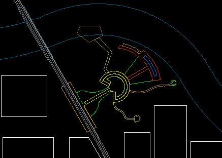
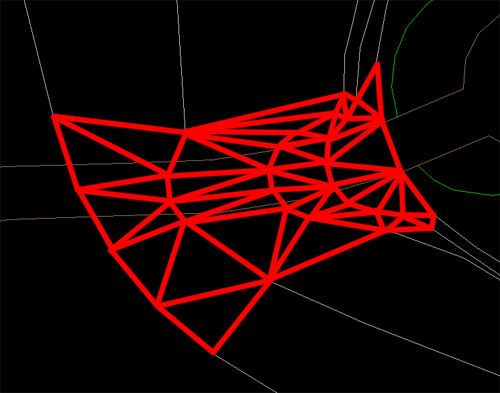
The first thing to realize is how SketchUp (or any other program) will create your topography.  As a quick intro/refresher- all 3d models are comprised of polygons- more precisely, triangles.  That is because 3 points makes a plane, and computers, as amazing as they are, cannot make true curves.  They can make thousands of tiny angles, but not an actual curve (there are ways to fake it more, but its still really a post production fake).  That is why when you make a curve in CAD and then zoom in it is suddenly angled lines that are kind of in the wrong spot.  Getting back to the point- your computer will make the smooth, rolling landscape by making a bunch of triangles and “softening” the edges, but it is still made up of triangles. These triangles are made by drawing lines from intersections on one line to intersections on another line.  For example, with these lines:

topoexample

This is (hopefully) where the triangles would be made:

topoexample2

This means 2 main things for your drawing.  First, and easiest: the further the camera is, the less detail that you will see, so by simplifying the lines that the triangles are made from, you reduce the number of triangles, and decrease rendering times.  So, when you are getting to areas that are far out of your model, and don’t need a lot of detail because they will act simply as context, you can often get away with making those smooth curves into sharp angles, and get nearly the same result for far less CPU power.

The second, and more tricky point: if you have a flat terrace, on your topography map that is shown by an area with a bigger spread in its contours, because we interpolate a steep slope suddenly being flat as essentially a level slope, even if the contours imply a 5% slope, because the slope is likely steep beyond the last “steep” contour.  However, the computer only sees what you put in, and cannot interpolate unevenly spaced contours, so it will have a slope that is steep from one contour the next, and then makes a hard turn to a 5% slope, and then a steep drop again.  Because of this, you have to edit your contour layer, and break one of the cardinal rules of topography- you are going to have a contour line split and then rejoin.  to create a truly level area you are going to have to surround the entire level area with equal contour lines, forcing the computer to see the contour lines your mind is reading between the lines on the map.

Level area the way its drawn on a map:

terracebadblank

The way that would be interpreted by a computer:

terracebad

The “fix” by breaking the rules:

terracefixedblank

The new triangle map (level area skipped for clarity):

terracefixed

Step 3: What is that path going to look like exactly?

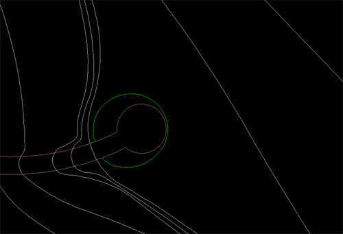
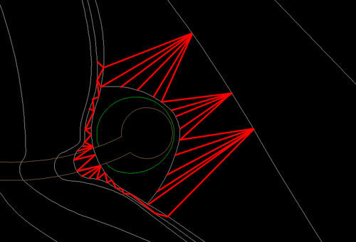
The last big complication to 3d modeling on topography is getting your paths and areas that overlap topographic changes to look right on the slope.  The problem is, again, the fact that the surface of the ground will be made of triangles.  this becomes an issue because your triangles may not line up with the edges of materials.  There are a few things you can do to address this.  First, you could simplify your topography so that a minimal amount of it intersects site amenities, as I was able to do in my thesis project, as there are not many large grading changes other then wetlands.

university

At times, however, that is not a viable option, and you need to be able to control what your slope looks like on a given face.  To do that you need to ensure that a given section of slope is laterally level.  The first step for that is to edit the contours so that the slope crosses the area in a straight line perpendicular to the slope.  This is what my topography looks like after I add my loops for level ground:

curvingtopopath

You want to change all of the sloping areas here:

curvingtopopathhighlight

To look like this:

curvingtopopathfixed

Once you do this, you wait for further fixing until you are in SketchUp, and that will come next week…

Step 4: Elevate to a New Level

The next thing you have to do is elevate your topography and items to the levels they will be at.  In AutoCAD, you want to open the properties window for each contour line individually.  Once there, you will see an option for “elevation”.  This is where you input the height of a given contour line.  Go through each contour line, and object and assign them to the appropriate elevation.  I personally like to also change them to a set color, like magenta, so I know what I have moved.  Then once everything is adjusted you can select all and move the color back to “by layer”.

elevation

magenta

magenta3d

Once you have everything moved to the correct elevation, you can change the color back, and finish the fix for uneven paths.

Now its time to import into SketchUp and let the real fun begin…